
Hazardous Area Exd, Ex e, DIP
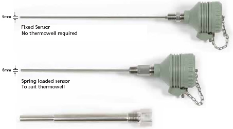
Thermocouples and RTD Sensors are an Ignition Source
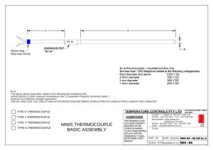
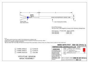
RTD and Thermocouple sensors are considered to be simple apparatus and when fitted with appropriate barriers may be installed freely in IS Circuits, ( Ex ia ) no further certification is necessary.
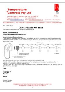
However the RTD and Thermocouple Sensors must meet the requirements of; AS/NZS 60079.11: 2006 Explosive Atmospheres Part 11 Equipment Protection by intrinsic safety ’i ’ Section 6.3.12 Dielectric strength requirement “ 500 VAC RMS Test Voltage of Insulation Resistance between Conductors or Conductors and Sheath for 2 minutes “
Thermocouples ( insulated junctions only ) and RTD Sensors manufactured will be subjected to the following tests:
- Visual and Dimensional Inspection
- Insulation Resistance Minimum 1000 M Ohms
- Upscale Polarity Test
- Electrical Continuity Test
| Part No TCTXEXI | Transmitter Head Mounted 2 Wire Hart Protocol Ex ia (IECEx Approved) | ||
|---|---|---|---|
| IPAQ 202X | 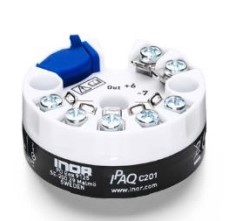 | ||
| IPAQ 330X | | ||
| IPAQ 520X | 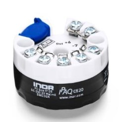 | ||
| IPAQ 530X | | ||
| Multi Input Thermocouple and RTD | Data Sheet SD 1836 IECEx Certificate SD 1837 |  | |
IECEx Certification
Certificate of Test 1047 will be supplied, there are a number of variations depending upon equipment supplied.
- SD 1047
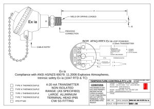
- SD 145 Ex ia
- SD 050 Ex ia
- >SD 012 Tx Ex ia
There are a number of sales drawings available and have a Ex ia Suffix added to the relevant SD number.
All thermocouples and RTD sensors in the price list meeting the requirements can be offered. The sensor will have a label attached .
Transmitters
To compliment these we have available the TCA range of IECEx Approved and in head 2 wire transmitters.
Product Drawings
Do you know?
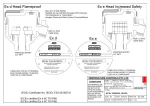
Ex d Flameproof Protection (Use in zones 1 & 2)
All electrical connections and equipment are enclosed in a housing strong enough to contain any explosion or fire that may take place inside the housing.
Ex tD Combustible Dust Protection (Use in zones 21 & 22)
All electrical connections and equipment are enclosed in a housing limiting the maximum surface temperature of the enclosure and restricting the ingress of dust by using dust tight or dust protected enclosures.
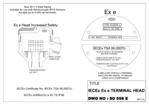
Ex e Increased Safety (Use in zone 2)
All electrical connections and equipment incorporate special measures to reduce the probability of excessive temperatures and the occurrence of arcs and sparks in normal service.
Ex ia Intrinsically Safety (Use in zones 0, 1 & 2)
The electrical energy available in circuits and equipment, is limited to a level too low to ignite the most easily ignitable mixtures in a hazardous area. Intrinsically safe barriers, Zener or Transformer Isolated, are installed in the circuit to limit current and voltage in the hazardous area to prevent sparking under fault conditions.
Drawings and documents
64 drawings and documents in this family
-
1047, CERTIFICATE OF COMPLIANCE Ex ia
Listed by TC as the certificate of test for Ex ia sensors
-
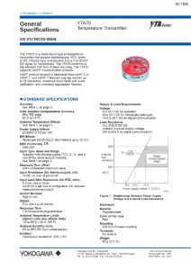
SD 1836
Listed by TC as the datasheet for transmitter TCTXEXI
-
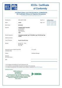
SD 1837
Listed by TC as the IECEx certificate for transmitter TCTXEXI
-
SD 575TW
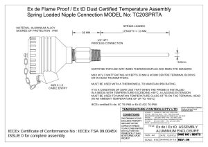
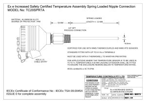
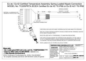
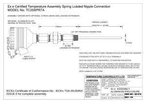
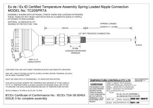
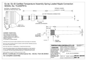
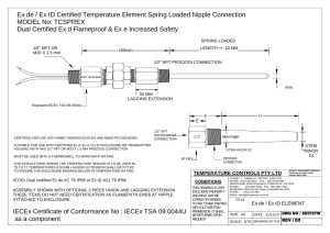
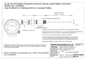
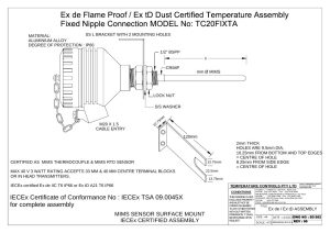
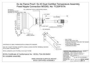
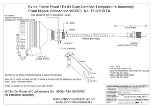
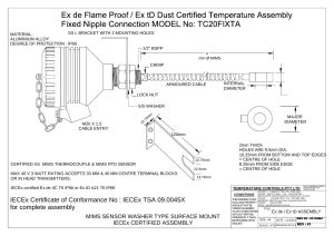
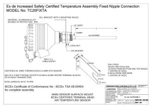
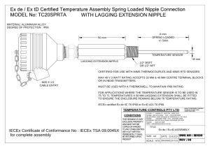
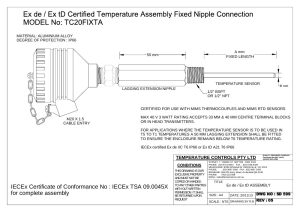
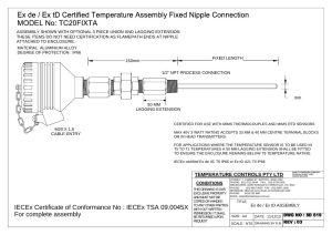
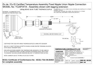
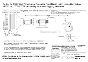
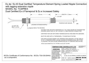
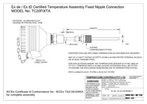
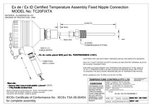
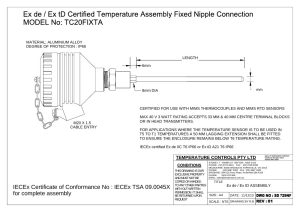
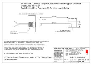
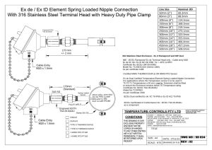
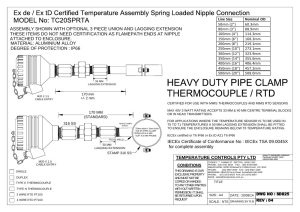
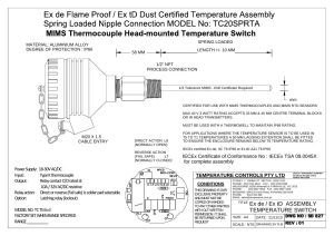
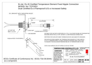
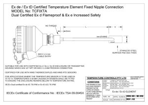
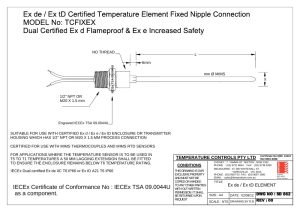
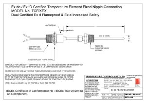
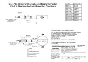
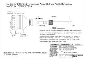
Ex de / Ex tD assembly
-
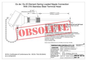
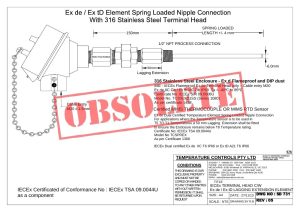
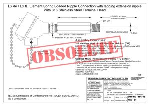
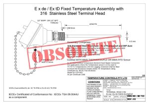
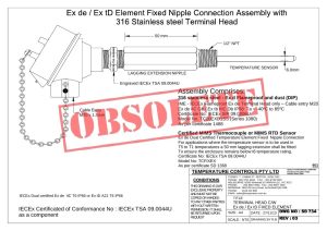
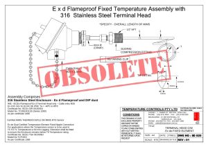
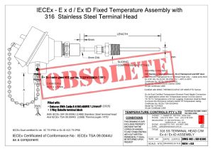
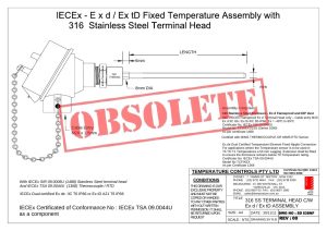
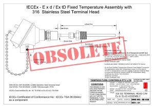
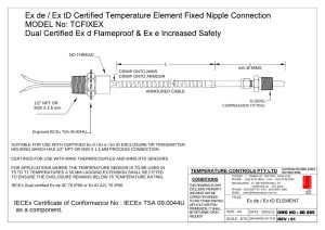
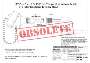
SD 838 – OBSOLETE
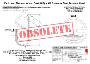
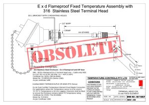
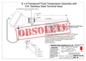
316 stainless steel terminal head with Ex d / Ex tD assembly
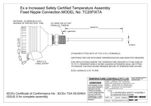
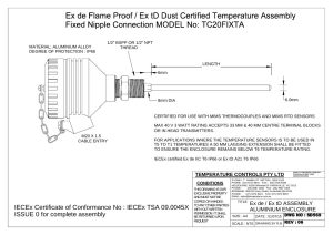
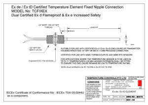
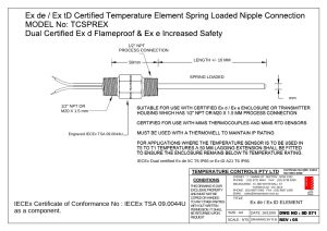

No matching drawing. Check the number, or search every document.